The Gorilla Microarchitecture
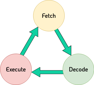
After we have successfully defined our ISA we can define one (of many!) microarchitectures in this section. In the introduction we defined the instruction cycle, to repeat: every instruction goes through the same phases. As designers, we can orientate ourselves on this and work through these phases one by one. The processor does nothing other than fetch, decode and execute instructions until it is switched off. On the right-hand side we see the instruction cycles again, but the individual states are now marked in colour.
Detailed explanation
Firstly, the instruction must be fetched. This means that an instruction must be loaded from a given memory address. After we have loaded this, it is decoded. Here the instruction is broken down into its individual fields (opcode, register source operands, immediate value). This information is used to select the correct registers and perform the appropriate operation. In the last step, the operation specified in the opcode is executed. The results are then stored in their corresponding destinations, for example in a register or in the main memory.
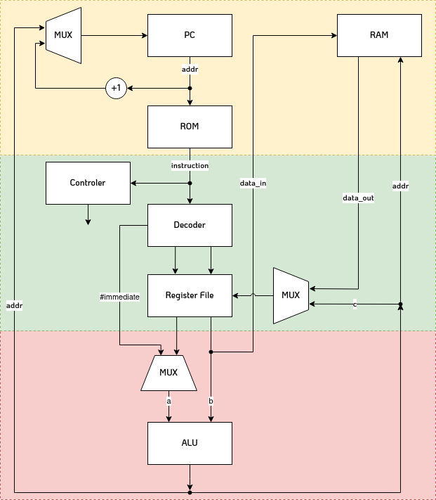
Proposed Microarchitecture
On the right side we find the proposed microarchitecture for our processor. As we can see, parts of the diagram are marked in colour. The colours correspond to the states and their colours which we have defined for the instruction cycle. Not all signals are shown for the sake of clarity, such as the clock signal or the inputs of the individual blocks for control signals
The processor consists of a total of 8 modules (PC, ROM, controller, ...) which we will implement one by one in the next step. We will start with the upper part (fetch), then the middle part (decode) and finally the lower part (execute)