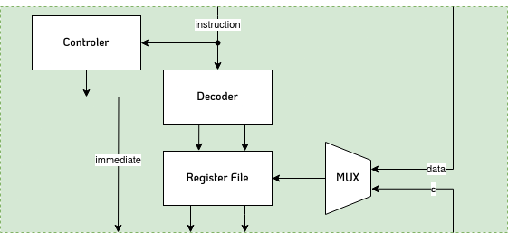
Decode
After we have fetched the instruction, it must be decoded. This involves interpreting the instruction, represented as a binary sequence, divided into opcode, register operands and immediate values, addressing the corresponding registers and setting the required control signals.
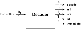
Decoder
The decoder has a relatively simple task, the instruction is divided into opcode, register and immediate values. These signals are forwarded accordingly. Even if a given instruction does not require two source registers, we still address them. There is no disadvantage to addressing them, as the controller ultimately decides which operands are combined and how.
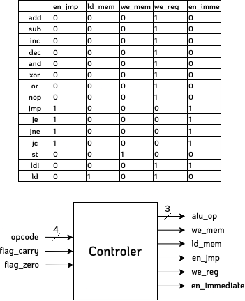
Controller
Probably the most important component of our small processor is the controller. The controller decides whether jumps are to be executed, which operation is to be carried out, whether results are to be saved in the file register or main memory and whether data is to be loaded from main memory.
On the right side you can see a table which shows how the control signals have to be set depending on the opcode. As an example the "ld_mem" signal, which decides whether the byte to be written to the destination register (rd) should be taken from the memory or from the ALU and is used as a control signal for a multiplexer. There are a total of 5 control signals which are set every clock cycle.
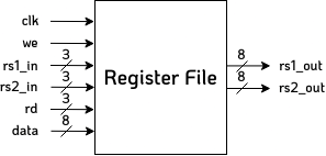
Register File
The register file reads the addressed registers every clock cycle and outputs them. Depending on whether the we (Write Enable) signal is set, which comes from the controller, data is also written to the destination register. 8 registers are available, each of which can store one byte.